Grade Level
3, 4, 5, 6, and 7
Difficulty
Easy
Duration
45 minutes
Subjects
Computer Studies
Craft
Engineering
Fun
Science
STEAM
Summer Camp
Vocab
Electric Current
Power Source
Switch
Circuit
LED
Author
Glowforge
Licensing

Lesson for Download
Overview
In this lesson, students will:
- Laser Cut the acrylic parts
- Build circuit blocks
- Assemble blocks into circuits
- Explore properties of circuits
- Examine conductive properties of different and materials
Objective
Creating battery-powered circuits that illuminate LEDs is a fun way for young kids to experiment with and learn about electricity. The tricky part of letting children investigate circuits is finding an accessible way for them to connect electrical components together. Alligator clips provide a simple, easily constructed electrical pathways, but most circuit elements use wires, which are small, fiddly, and tricky to connect to clips. This project describes how to create “circuit blocks,” which provide a straightforward way to connect alligator clips to circuit elements like batteries and LEDs. In this tutorial, all electrical connections are made with copper tape and no soldering is required. Children will be able to use circuit blocks to explore and build different circuits which illuminate LEDs and investigate the conductive properties of different objects.
Supplies
MATERIALS & TOOLS:
- Proofgrade clear acrylic sheet
- ¼” Copper tape *that is conductive on both sides*
- 12 mm M3 Screws and M3 nuts (2 screws and 2 nuts for each circuit block)
- Several 5 mm standard LEDs in any color
- 330 Ohm resistors (one for each LED circuit block)
- Battery holder/connector with wire leads. It should provide voltage between 3V and 9V. For example, any of the following will work:2xAA Battery Holder (3V)
- 3xAAA Battery Holder (4.5 V)
- 9V Battery Clip (9V)
- Alligator clips
- Batteries
- Laser Cutter
- Wire Stripper
- Wire Cutter
- Fine-nose Pliers
- Screwdriver
Design Files
Description
Lesson Outline:
Following the Design Thinking Process
BUILD – Introduce the lesson plans and prompt for current knowledge
EXPLORE – Decide on an idea to pursue and prototype.
TEST – Students test their prototypes to see if it works
EVALUATE – Students reflect on their process to see if it worked.
Lesson Instructions
Step 1: SETUP
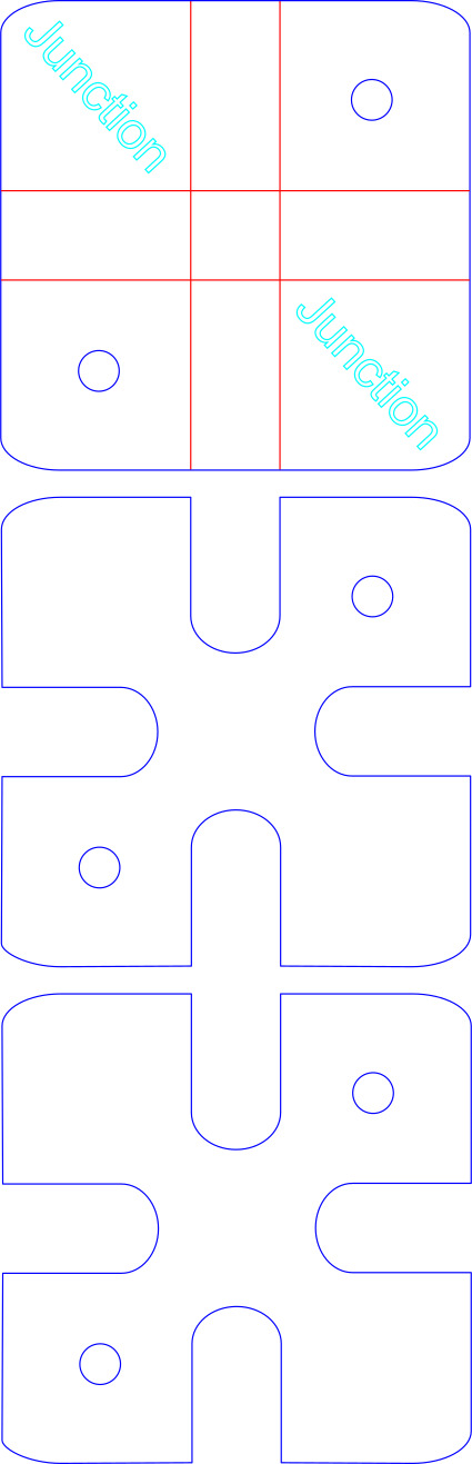
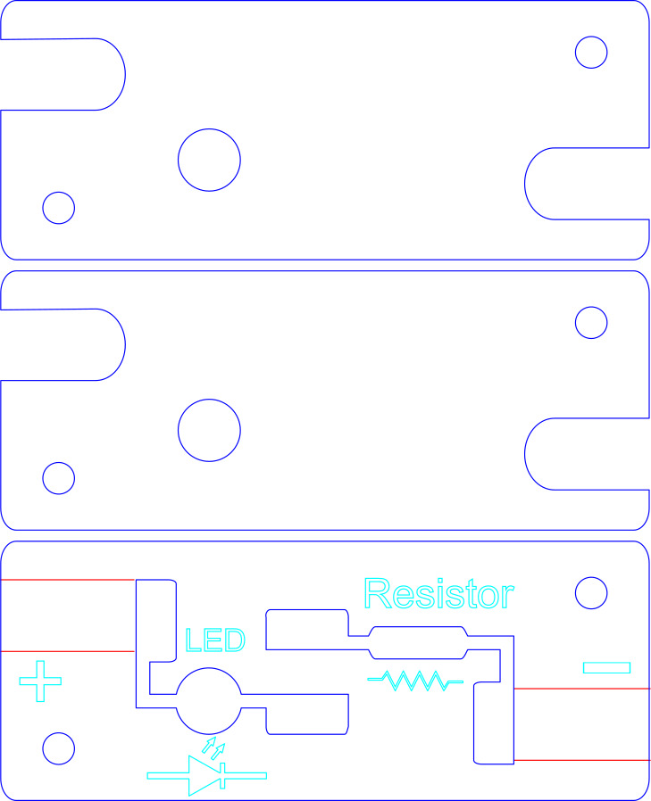
Laser Cut the Pieces Description Laser cut the acrylic pieces for the battery block (file “BatteryBlock.svg”) and the LED/resistor (file LEDResistorBlock.svg”)block from 1/8” acrylic sheet. The blue lines are for cutting, red lines are to be etched as lines into the acrylic, and teal lines are for creating filled etched shapes. Each block has a central layer which contains the electrical components and conductive copper tape as well as two protective acrylic layers which provide guides for connecting alligator clips. After cutting, peel off any protective paper from the cut acrylic.
Step 2: Build the Battery Block
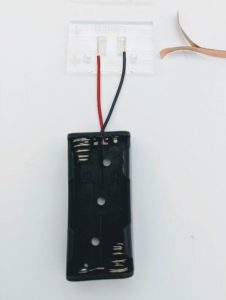 Inspect the battery case and be sure any batteries are removed. The case shown here holds 2xAAA batteries, but any holder/connector with wire leads will work. Trim the leads to a manageable length and strip off about 3/8” insulation from the end of each lead with wire strippers. Three pieces of acrylic will stack to form the battery circuit block. The middle layer is the piece with writing on it. Place the ends of the wires in the two slots as shown. The red wire goes in the slot nearest the “+” sign and the black wire goes in the slot nearest the “-“ sign. The stripped ends should be about the same length as the rectangular cutouts.
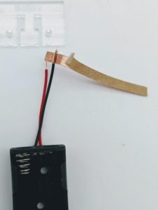
 Remove the wires from the acrylic and cut a piece of copper tape about two inches long. Peel any backing from the tape and lay it on a flat surface, sticky side up. Place the stripped end of the black wire on top of the sticky side of the tape – about 1/4” from the end. Fold the short end over the wire as shown, and, using your fingertips, pinch the tape firmly around the wire a few times. This is important to ensure good contact and electrical conduction. It is extremely important that the copper tape you are using is conductive on both sides, or the current will not flow from the wires through the tape.
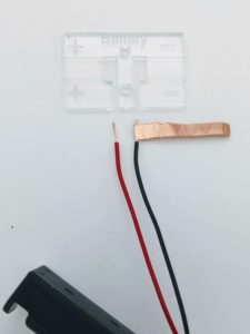
 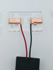 Place the black wire in the slot in the acrylic from below. Be sure the black wire goes into the slot nearest the “-“ sign. The end of the wire should just touch the top of the square slot. The copper tape will stick to the bottom of the acrylic. Continue to wrap the tape around the edge of the acrylic and down again through the slot containing the wire. The tape should wrap around at least two times. If it is a bit too short, then wrap another layer of tape on top of the first. Repeat this process with the red (positive) lead. The acrylic piece with the leads should look like the picture above:
 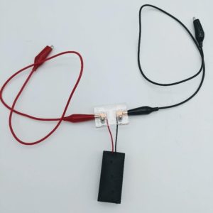 Take the remaining two pieces of acrylic for the battery holder and sandwich the piece with the copper tape between them. Use the 12mm M3 screws and nuts to secure all three acrylic pieces together. Alligator clips can now be easily and securely connected to the notches in the side of the battery circuit block as shown. You may want to create different battery blocks connected to holders of different voltages (i.e. one 3V block as shown and a 9V block using a 9V connector) to have more flexibility in creating different kinds of circuits. Warning: when using the battery circuit block, be incredibly careful to never connect the positive and negative terminals together directly or let leads connected to the terminals touch each other. The rush of current through the leads can cause burns or other injuries. Build the LED/Resistor block: The battery block provides power, and an LED/resistor block will provide an element with which to complete the circuit. The LED/Resistor block actually contains two individual circuit elements – an LED and a resistor. The LED (Light Emitting Diode) lights up when current passes through it, and the resistor reduces the amount of current passing through a circuit. A resistor is necessary because most batteries provide more current than a standard LED can handle and will cause the LED to burn out if connected directly
 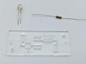 LEDs only allow current to flow in one direction, so it is important to insert the LED into the circuit block with the correct orientation. The legs of most standard LEDs are different lengths. By convention, the longer leg is the positive one. In the picture above – the left leg of the LED is the positive lead.
 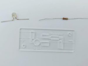 Place the LED near the center circuit block layer (the one with the writing on it), and, using the pliers, bend the legs 90 degrees outwards, a few mm below the base of the LED. Orient the LED so that the positive leg is towards the left side of the block as shown in the picture above.
 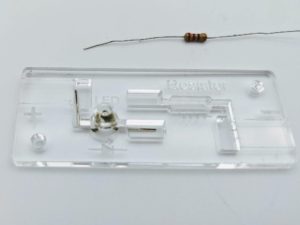 Place the LED in the block so that the light emitting portion sits just above the round hole and, using pliers, bend the two legs to fit the channels on either side of the center hole. The positive LED leg sits in the vertical (leftmost) channel. The LED “bulb” will sit a few mm above the acrylic. Using the wire cutter, trim any parts of the leg which extend past the ends of the channels.
 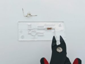 Place the resistor in the acrylic layer so that its center portion fits in the oblong slot. The orientation of the resistor doesn’t matter. Using pliers, bend the resistor legs to fit in the long channels on either side of the slot. Using wire cutters, trim the ends of the resistor legs which extend past the ends of the channels.
 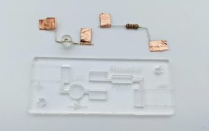 Next, remove the LED and resistor from their slots, being careful to keep the legs of both bent into the same configuration. Cut four pieces of copper tape about ½” long each. Peel the backing from each piece and fold them over the ends of each wire in the LED and resistor as shown. Press the copper tape firmly between your fingertips a few times to ensure good contact between the tape and the wire.
 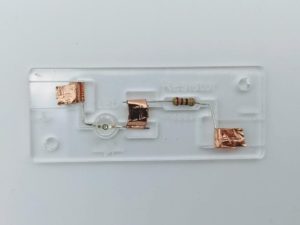 Once the tape is applied, set the LED and resistor back in their respective slots.
 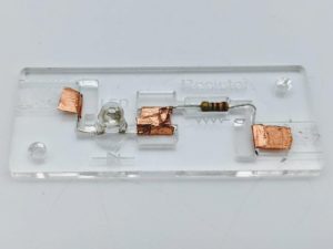 To connect the resistor to the LED, cut a piece of copper tape about 1” long, peel off the backing, and wrap it through the two slots in the center of the acrylic piece so that it envelops the copper tape “flags” on the resistor and LED. Wrap the tape through the center slots a few times and press it down firmly to the acrylic with your fingers to ensure good electrical connection. Use your fingernail or the end of the screw driver to push the tape down against the end of the wires inside the slots.
 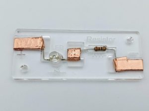 Next, cut two pieces of copper tape about 3” in length, and wrap them several times through the side channels and around the edges of the acrylic as shown above. Once wrapped, press the copper tape firmly to the acrylic with your fingers to get rid of any air bubbles and insure a good electrical connection. Use a fingernail or the end of a screwdriver to press the tape firmly against the wires in the LED and resistor.
 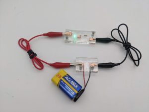 Before fully assembling the LED/Resistor block, test it to make sure all connections are good. Take the Battery Block you made previously and insert/connect the batteries. Using two alligator clips, attach the positive battery lead to the copper tape nearest the “+” sign in the LED block and attach the negative lead to the copper tape nearest the “-“ sign on the LED block. If all connections are good, the LED will light up. If it doesn’t light up at first, leave the power connected while you carefully smooth out and press down on all the places the copper tape makes contact with a wire. The contact needs to be good for the electricity to flow through the circuit, so press down on all connections carefully and firmly until the LED lights up. Once the LED/Resistor block is working up, complete the block by placing the top and bottom acrylic layers around the middle layer – carefully slotting the dome of the LED through the hole in the top layer. Fasten all three layers together with 12mm M3 screws and nuts. The Battery and LED/Resistor blocks together create a simple circuit. To allow for more complex circuits, you may want to assemble one or two additional LED/Resistor blocks.
Step 3: Explorations
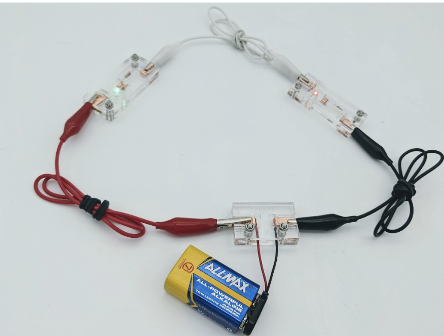
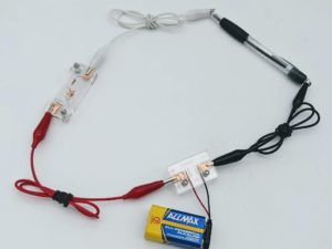
Circuits/Disodes Have students construct a simple circuit with a Battery block, LED Block and alligator clips and watch as the LED lights up. Point out that the electricity flows from the positive terminal of the battery (labelled with a “+” sign) back to the negative terminal (labelled with a “-“ sign), passing through any circuit elements in its path. Un-clip just one of the alligator clip leads and watch what happens to the LED. Ask the students why it is no longer illuminated, even though one end is still connected to the battery. Discuss with the students that electricity must flow in a path that leads it back to the negative terminal of the battery. Electricity must flow from a higher voltage to a lower voltage – a bit like water must flow from a higher level to a lower level. A pool of water all at the same level won’t flow anywhere. Similarly electricity will only flow where there is a voltage difference. 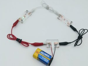 Try connecting the circuit again but insert the LED block with the opposite orientation. This won’t hurt the LED, but the LED won’t light up. The letters “LED” stand for “Light Emitting Diode”. A diode is a kind of circuit element which only allows electricity to flow in one direction. If you have more than one LED block, have students build a circuit where the output of one LED block connects to the input of a second LED block as shown above. Because each LED reduces the voltage about 1.8V between its input and output, you will need a power source of 4.5V (3AA or 3AAA batteries) or 9V (one 9V battery – as pictured) for it to work. This kind of connection is called a “Series Circuit” in which the electricity passes through each circuit element in turn.
Step 4: Conductivity Testing
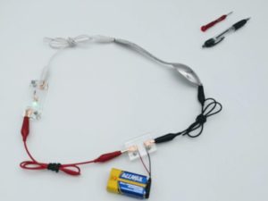
 Create a series circuit with the Battery block and one LED block. Using an extra alligator clip, try connecting different objects in series with the circuit as shown. If the LED lights up, the object is conductive, i.e. electricity can flow through it. The images above show that a spoon is conductive but a ballpoint pen is not. Try connecting to objects constructed from different materials – metals, plastics, wood, etc. Ask the students what their experiments reveal about the conductivity of various materials.
Step 5: Evaluate
Discuss with the students what they have learned about circuits, electricity and LEDs. Ask the students to name ways in which circuits are used everyday – in houses and vehicles, for examples. All circuits work by causing electricity to flow from a higher to lower voltage, passing through different electrical components. There are many kinds of electrical components which can be used in electrical circuits. Other tutorials in this series contain instructions to build additional types of circuit blocks which can be combined with Battery blocks and LED/resistor blocks to create more complex and interesting circuits.
Meet Glowforge
The magical 3D laser printer that made this lesson possible. Learn more!